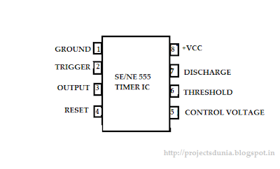
Pin Diagram Of 555 Timer Ic
555 ic timer circuit diagram astable pinout pins multivibrator block description ic555 internal monostable using circuits ground board explain power 555 timer ic as a-stable multivibrator 555 timer ic circuit integrated diagram working projects board works electronic time components principle choose used
A complete basic tutorial for 555 timer IC - Electronic Circuit Collection
555 timer ic: introduction, working and pin configuration Ic timer block diagram introduction working configuration Diagram timer schematic makingcircuits pinout
555 timer ic: introduction, working and pin configuration
555 timer electricaltechnology pinout schematic applications operation555 timer circuits configuration circuit diagram inside drawing trigger symbol led light ground voltage make 555 timer icTimer ic.
Ne555 monostable circuits electrical internal ics bistable multivibrator tester mv timing555 timer ic working principle How does ne555 timer circuit workDesigns & schematics.

Integrated circuit chip identification
Pin on 555 timer circuitsTimer ic diagram multivibrator stable 555 cmos invention circuitstoday lm555Delay proteus.
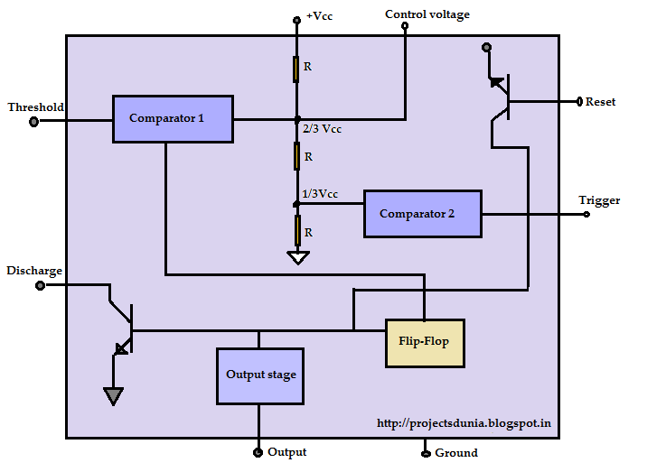
555 timer ic: internal structure, working, pin diagram and description555 timer ic pin diagram and internal circuit 555 timer ic circuits diagram using circuit block functional unusual special trigger schmitt external simple figure within lines double use555 timer astable circuit multivibrator schematics schematic circuits ne555 stable output timers.

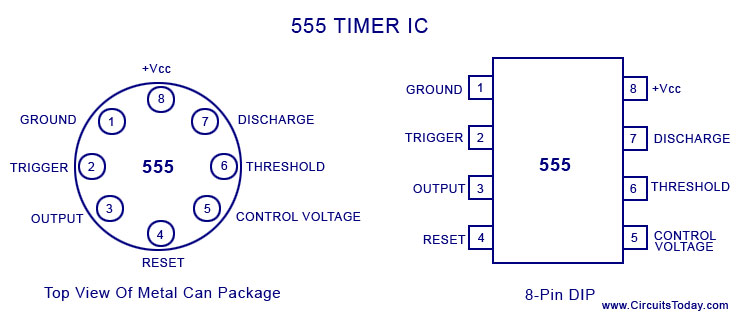
Pin configuration of the 555 timer
The history of 555 timer ic555 timer ic Timer ic diagram history dual invention story ics555 timer ic.
How a 555 timer ic works555 timer ic configuration basic diagram package complete datasheet data sheet block logic dip metal tutorial circuit guide projects working Introduction to the 555 timer555 timer ic schematic diagram / the 555 timer can provide time delays.

Timer 555 ne555 datasheet pinout block ic does eleccircuit flop astable lm555
555 timer icTimer ic working principle diagram block circuit 555 timer ic working, pin diagram, examples (astable, monostable, bistable)The history of 555 timer ic.
Using the “555” timer ic in ‘special’ or unusual circuitsTimer diagram ic functions Ic 555 timer configuration working introduction dip555 lm555 astable integrated configuracion diagrama tp3 datasheet utmel.

A complete basic tutorial for 555 timer ic
.
.


555 Timer IC as a-stable Multivibrator

Designs & Schematics - Computers Rock
555 Timer IC: Introduction, Working and Pin configuration | PROJECTSDUNIA

How does NE555 timer circuit work | Datasheet | Pinout | ElecCircuit.com
555 Timer IC: Introduction, Working and Pin configuration | PROJECTSDUNIA
A complete basic tutorial for 555 timer IC - Electronic Circuit Collection
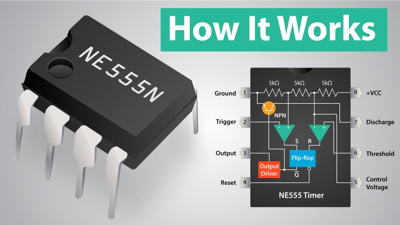
How a 555 Timer IC Works | Doovi