Ne555 Pwm Circuit Diagram
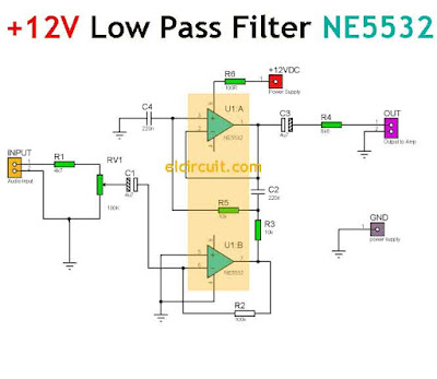
Circuit ne555 motor control diagram composed seekic ic frequency Ne5532 filter pass low 12v circuit subwoofer diagram amplifier power simple bass board speaker crossover dc pcb layout audio elcircuit Pwm ne555 circuit
Ne5532 Preamplifier Circuit Diagram - Project | Audio Blox: Experiments
Ne5532 power amplifier circuit diagram Pwm 555 ne555 circuit circuits electronics elettrico electronic polistirolo taglia circuito timer dimmer schematics modyfikacja kieszonkowa akumulatorowa transformatorowa mikrocontroller caldo Pulse modulation pwm circuitbasics
Pwm ne555 mosfet dimmer instructables circuits
Pwm with ne555Pwm ne555 circuit controle speed circuito schematic circuits usando amplifier circuitstoday How to generate pwm using ic 555 (2 methods explored)Schematic & wiring diagram: dc motor controller circuit with ne555.
Pwm ne555 12v pic circuits between two circuit signals difference schematicNe5532 preamp audio preamplifier lm1875 supply schematics Pwm ne555555 pwm circuits generate generating explored simplest below.
Pwm dc motor speed control using ne555
Pc-atx snt , ne555 pwm , buz11 , freilaufdiode, div. fragenNe555 adjustable pwm circuit Pwm ne555 timer ic circuit but oldschool p1 adjusted dynamic staticPwm 555 motor circuit dc control power supply speed 90vdc circuits timer astable fan battery circuito mosfet velocidad diagrama circuitos.
How to build a pulse width modulation signal generatorSchematic ne555 motors controller working power big circuitlab created using A low cost pwm dimmer using ne555 and mosfet with diy aluminium casePwm 555 analog signal timer requirement.

Ne5532 preamplifier circuit diagram
Motor control circuit composed of ne555 .
.

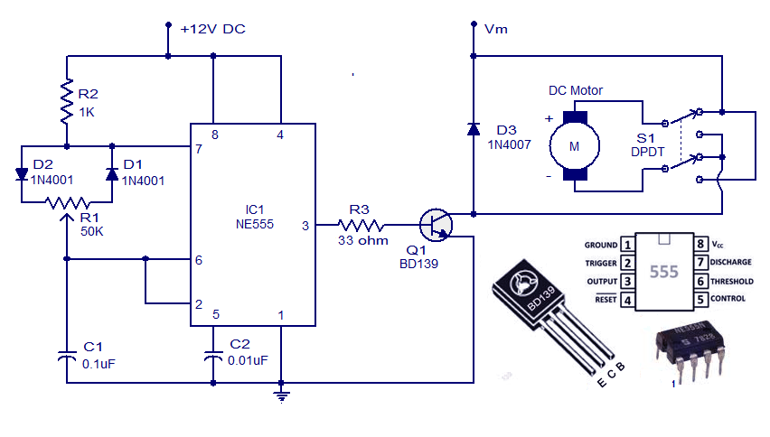
Schematic & Wiring Diagram: DC Motor Controller Circuit with NE555

NE555 Adjustable PWM Circuit - General Electronics - The Contextual

a low cost PWM dimmer using NE555 and MOSFET with DIY aluminium case

timer - 555 PWM motor driver controlled by external analog signal

How to Build a Pulse Width Modulation Signal Generator - Circuit Basics

mosfet - NE555 power controller not working with big motors

PC-ATX SNT , NE555 PWM , BUZ11 , Freilaufdiode, div. Fragen

microcontroller - Difference between two 12V PWM signals/circuits (PIC
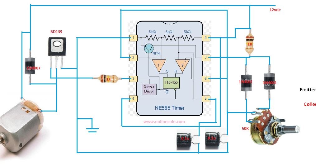
PWM DC MOTOR SPEED CONTROL USING NE555 | CIRCUIT DIAGRAM