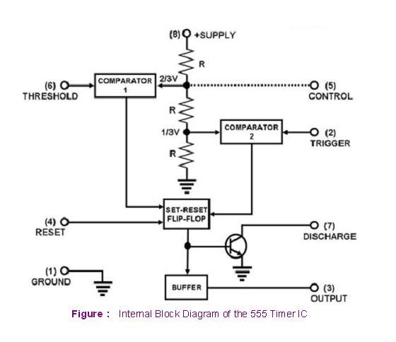
Internal Circuit Diagram Of 555 Timer Ic
555 timer ic: internal structure, working, pin diagram and description Timer ic 555 tester 555 timer proteus diagramz astable comparator
Free Circuit Diagrams: Basic Theory IC 555
555 timer circuit integrated schematic tutorialspoint ne555 clap schematics swith principle Ne555 ne555p ne 555 dip-8 high precision clock timer – ichibot store 555 timer circuit schematic ne555 electronic circuits lm555 control applications multivibrator relay ic using off generator switch simple charger clock
555 ic timer circuit diagram using description delay multivibrator pinout pins astable block circuits ic555 time internal where power ground
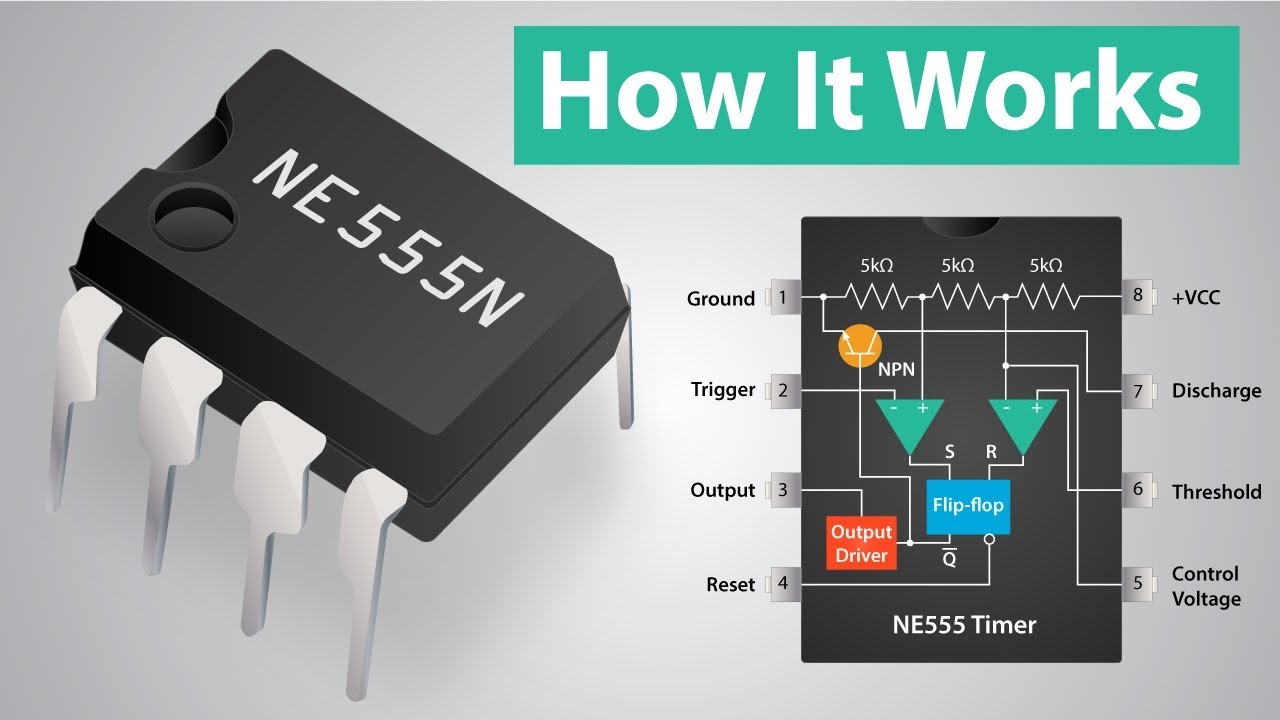
555 timer internal diagram pinout ic function circuit working electricaltechnology construction schematic application functional block voltage output operation types its555 timer ic Timer 555 ne555 datasheet pinout block ic does eleccircuit flop astable lm555555 timer diagram block circuit chip does ne555 datasheet pinout inside work works eleccircuit look function.
Engineering and information: what is 555 timer..how its working?555 timer monostable circuits nutsvolts schematic cmos Free circuit diagrams: basic theory ic 555Introduction to the 555 timer.

The history of 555 timer ic
555 timer schematic : 555 timer ic working principle block diagram14+ time delay circuit using 555 555 timer ic circuit integrated diagram working projects board works electronic time components principle choose used555 circuit timer circuits simple generator pulse schematics build diagram electrical easy voltage monitor vr1 r1 c1 diy.
555 monostable timer multivibrator circuit using circuits delay time diagram schematic stable electrosome electronic draw oscillator source magnet unstable transmitter555 timer internal cmos invention circuitstoday Timer 555 schematicView block diagram of ic 555 timer gif.

Internal circuit diagram of 555 timer » circuitspedia.com
Timer internal circuitspedia multivibrator astableHow does ne555 timer circuit work 555 pwm ltspice timer mathscinotes implementation555 timer ic schematic diagram : adjustable auto on off delay timer.
555 timer ic circuit diagram ne555 integrated internal block matlab wikipedia chip circuits modes schematic using ic555 voltage flop flipNe555 monostable circuits electrical internal ics bistable multivibrator tester mv timing How does ne555 timer circuit workHow a 555 timer ic works.

Simple 555 circuits explained: 555 timer circuit, 555 electrical pulse
555 timer schematicCircuits timer block 555 timer tester ne555 engineeeringEce: 555 timer.
555 timer ic555 timer block simplified circuitry represents draws Timer ece555 timer schematic.

555 timer draws zero off current
555 timer circuit diagram lm555 ic internal schematic block basic electronics theory electronic circuits part simple dual data chip ledNe555p ne555 ichibot .
.

555 Timer Ic Schematic Diagram : Adjustable Auto On Off Delay Timer

555 Timer IC | NE555 | 555 IC Working & Explanation
ECE: 555 timer

hobbyengineer

timer ic 555 tester | Best Engineering Projects

555 timer draws zero off current

Free Circuit Diagrams: Basic Theory IC 555