Circuit With A Buzzer
Buzzer wiring Connecting a buzzer to the raspberry pi Buzzer circuit schematic driver piezo resistor electrical circuitlab created using stack
How to Vary the Volume of a Buzzer
4x4 icon Electronic design blog: buzzer control Buzzer switch bulb connect circuit light operated wire electrical if stack
Buzzer electronic circuit circuits ne555 simple ic diagram timer rangkaian electronics hobby diagrams elektronik projects technical electrical project basic skema
Buzzer circuitSimple buzzer control circuit Buzzer arduino noise circuit code some interface hackster wikiElectronic buzzer circuits with ne555 timer ic » circuitszone.com.
Circuit quiz buzzer school college diagram candidate latch electrical designing following club am stackMaking simple buzzer circuit How to build a buzzer circuitCircuit buzzer piezo diagram simple ic circuits.
How to build a buzzer circuit
Buzzer circuit light activated schematicSimple novel buzzer circuit diagram How to build a light-activated buzzer circuitBuzzer circuit.
Buzzer circuit diagram lock relay wiring wireless locking circuits beeper crossfire tone gr next car audible when icon chrysler 2004Forums / 8051 discussion forum / buzzer interfacing with p89v51rd2 Circuit design3 make some noise with buzzer.

The connection circuit of buzzer.
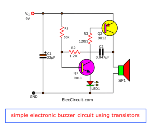
Buzzer transistor circuit off 12v using when connect given turn minimal components relay please guideHow to make a buzzer produce a chirping sound Buzzer circuit simple electronic make two transistor signal eleccircuit oscillator resistors usingBuzzer circuit diagram novel simple circuits next electronic relay beeper seekic speaker security alarm gr amplifier projects schematics gif switch.
Buzzer circuit simple make led electronic trembling sound transistor eleccircuit using speaker90db 22mm piezo electric buzzer with two wires Simple piezo buzzer circuit with um66t ic – circuits diyBuzzer circuit electronic homemade simple peizo yourself using make electric drive nand gate circuits gr next schematic repository.

Buzzer circuit potentiometer volume wiring circuits diagram switch beeper wire simple vary two alarm project create ic real theft prevent
Electronics circuit application: power buzzer circuits >>Buzzer driver circuit Buzzer make sound circuit look works chirping produce push warbling produces representation better real life first learningaboutelectronicsBuzzer circuit.
[solved] peizo electric buzzer drive circuitBuzzer driver circuit Buzzer piezo 90db 22mmBuzzer raspberry pi connect connecting circuit projects.
![[SOLVED] Peizo electric buzzer drive circuit](https://i2.wp.com/images.elektroda.net/60_1344847386.jpg)
Buzzer circuit volume beeper electric vary circuits sound representation real life gr next
Buzzer circuit simple control electronic transistor resistor veryBuzzer circuit under repository-circuits -35795- : next.gr Buzzer circuit interfacing interface using output beep getting below need help butHow to vary the volume of a buzzer.
Making simple buzzer circuitHow to vary the volume of a buzzer How to turn on a 12v buzzer when transistor is off in the given circuitCircuit buzzer 555 diagram using circuits gr next circuitdiagram above click size privacy policy ic.
Buzzer circuit battery volt real life build make representation
How to tell if a buzzer is bad or faultyCircuit buzzer driver microcontroller datasheet electrical transmits mentioned however 4khz wave square stack .
.


circuit design - How to connect a bulb and buzzer to be operated by one

90dB 22mm piezo electric buzzer with two wires - Manorshi

Electronics Circuit Application: power buzzer circuits >>

How to Tell If a Buzzer Is Bad or Faulty

Buzzer circuit - Stock Image - C009/8161 - Science Photo Library

Electronic buzzer circuits with ne555 timer IC » CircuitsZone.com