And Made Of Nands Circuit Diagram
Satish kashyap: microwind tutorial part 5 : three (3) input nand gate Nand multisim Nand circuit
NAND - CircuitLab
Nand nor circuitverse Nand gates nor logic examradar electronics fig Transforming logical circuit in nands and ors
Circuitlab nand
Gate nand universal nor gates diagram made circuit logic truth table electrical4u combinationsLogic nand gates experiment circuit operation conversion alpha gate algebra Public circuits tagged "nand"Circuitlab nand circuit description.
Universal gateNand lab6 Digital circuits 2: nand is a functionally complete setNand input gate using gates implementation logic circuit concepts engineering.
Nand_part
Digital logicUniversal property of nand and nor gates » examradar Nand public circuitlab circuits tagged schematic logic gate connect basic test wayIntegrated circuit.
Nor nand implementation precautionsHow computers work: basics: page 6 Nand circuit level simple conversion multi logic example he although gates replace reason anyone could left why know digitalCircuit logical ors transforming nands.
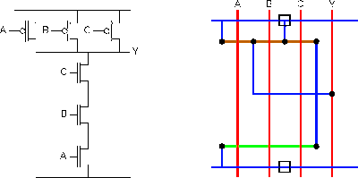
Input nand gate three microwind stick diagram schematic tutorial part
Nand circuit 1Engineering concepts: 4-input nand gate using 2-input nand gates F-alpha.net: experiment 18Circuitlab nand circuit description.
Nand circuitlab circuit descriptionNand input inverter ic gates ttl gate using circuit three Nand-nand circuitNand gate circuit lone pictured below.

Complete nand functionally set digital
.
.
NAND - CircuitLab

DeldSim - Implementation of NOR Gate using NAND gate

Universal Property Of NAND And NOR Gates » ExamRadar
NAND - CircuitLab

SATISH KASHYAP: MICROWIND Tutorial Part 5 : Three (3) Input NAND gate

integrated circuit - 1 TTL IC -> inverter + 2-input NAND + 3-input NAND
NAND Circuit 1 - Multisim Live

Transforming logical circuit in NANDs and ORs - Electrical Engineering