555 Ic Remote Control Circuit Diagram
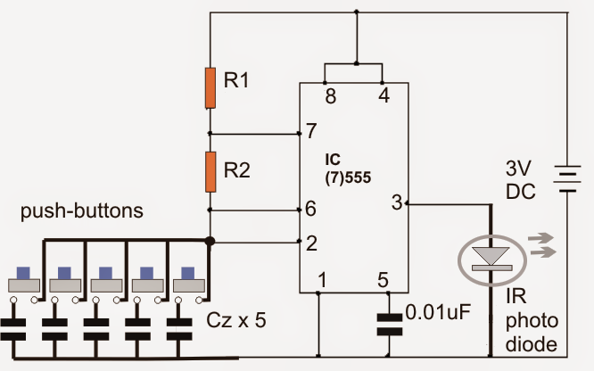
Remote control circuit for multiple appliances 555 timer circuit : other circuits :: next.gr Simple ir remote control circuit diagram
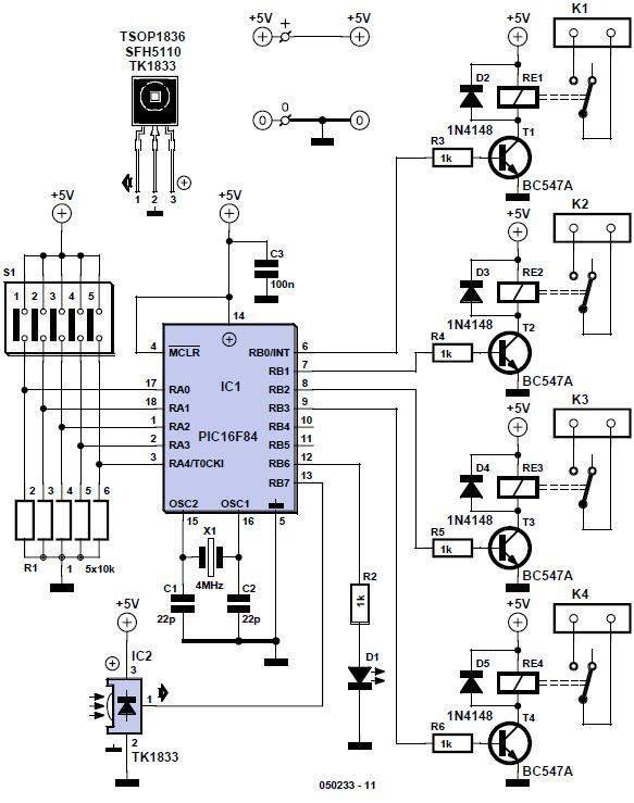
Infrared Remote Control for Home Appliances
Hobby in electronics: remote control regulated ceiling fan circuit diagram Remote controlled appliance switch circuit Ir remote control circuit diagram
Ir transmitter remote tsop1738 control circuit diagram led using range infrared appliances
Remote control ir appliances circuit diagram infrared receiverIr circuit remote diagram control transmitter infrared circuits Circuit ir diagram simple remote control receiverInfrared remote control for home appliances.
555 timer circuit page 14 : other circuits :: next.grAsk modulator using 555 timer ic Remote controlled fan regulator circuit5 pc power supply circuit for you.

Remote circuit control 567 lm ne circuits lm567 frequency diagram using channel ne555 schematic gr next electronic
Infrared remote control for home appliancesRemote control circuit for multiple appliances Home remote control circuit diagramCircuit remote control extender ir ic diagram circuits repeater wired timer infrared gr next simple following shows appliances location.
Tv remote control jammer circuit diagram using ic 555Fan remote control ceiling circuit diagram hobby electronics regulated relay regulator ac Circuit remote control ir appliances multiple using transmitter module diagram following controlling single555 timer circuit remote control jammer.

Circuit remote switch appliance control controlled circuits diagram wiring off gr next notes projects parts
20 easy ic 555 circuits for students and new hobbyistsInfrared remote control transmitters circuits Circuit fan remote regulator dimmer controlled switch ceiling circuits ic infrared simple pwm inverter using homemade electronic diagram controller projectsCircuit control level circuits timer gr next diagram consists shown step down.
Remote control switch circuitCircuit remote control appliances ir diagram multiple transmitter receiver 555 simple electronic keyboard circuitIc circuits easy hobbyists students.

Electrical engineering books
Circuit jammer remote tv diagram control 555 ic using timer explanation electronic circuitsCircuit keyboard simple electronic seekic ic diagram Remote infrared transmitter eleccircuit mihai agree configuration introduced thank555 distance remote control amplifier switch circuit.
Modulator timerRemote control circuit using ne555 & lm567 ~circuit diagram Circuit remote diagram switch off control controlled ic transistor signal q1 pnp amplified fed appliedCircuit control amplifier distance remote switch seekic.

555 timer circuit : Other Circuits :: Next.gr

Remote Controlled Fan Regulator Circuit

Infrared Remote control transmitters Circuits | ElecCircuit.com
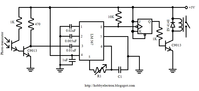
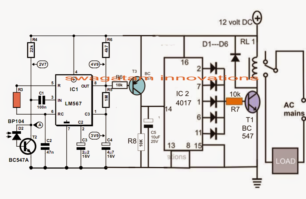
Remote Control Circuit using NE555 & LM567 ~Circuit diagram

Simple Ir Remote Control Circuit Diagram | Car Wiring Diagram
Remote Control Circuit for Multiple Appliances | Circuit Diagram Centre

Infrared Remote Control for Home Appliances
Home Remote Control Circuit Diagram - Electrical Engineering Books